Classic Game Station
Building a Retro Game Console Even Grandma Could Use
What is it?
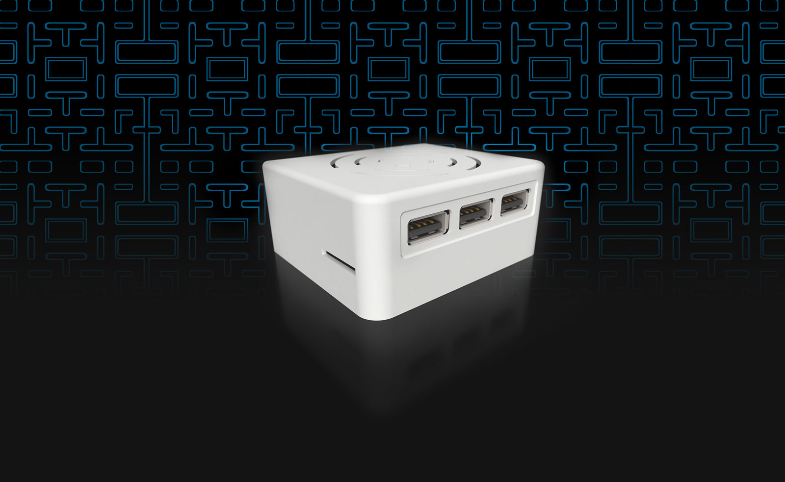
A small (less than 3 inches along its largest dimension) video game console device, based on the Raspberry Pi Zero, capable of emulating classic video games. Example systems include the original Nintendo Entertainment System (NES), Super Nintendo (SNES), Sega Genesis / Mega Drive, arcade games, etc.
Why build it?
Because old video games are awesome, and using an emulator on your computer isn't nearly as fun. In their time, these games were often enjoyed in people's living rooms. This project helps revive a piece of that nostalgia in a fun, sharable way that anyone (not just tech enthusiasts) can appreciate.
How much does it cost?
Excluding the TV (which you probably already have), it ends up costing around $70 USD when you include everything: the device itself, cables, power, an SD card and 2 (yes, two) gamepads/controllers. You could also skip some things and build it for a bit less, or add more features for a bit more.
What do I need?
Most of it can be built using off-the-shelf parts from places like Amazon.com many online stores (see note at bottom). For the enclosure, you'll need access to a 3D printer (or an online 3D printing service), a few standard tools, a short M3 screw (~ 8mm should be enough), and a soldering iron (optional if you want an extra power LED light).
Motivation and Research
As a fan of old video games, I'd been wanting to put together an emulator box/console for my home. My wife asked (ok, begged) me to finally make one, but she didn't want to deal with a mess of wires or exposed circuit boards whenever we wanted to play it. It also needed to be cheap and easy enough for other family members to use.
In the past, I put together various projects around the home using Raspberry Pis, so based on what I saw other people doing online, I figured I could easily use a Raspberry Pi Zero to accomplish the task. Seeing that the brains and software for the device would easily be fulfilled by a Pi Zero and some freely available software, I turned my attention to the case.
My other RasPi-based projects were perfectly content being housed in generic Raspberry Pi enclosures (or sometimes no enclosure at all) because they were out-of-view, so aesthetics didn't really matter. But this project was different.
For something that would visibly occupy space in the living room, the retro gaming console demanded more attention.
I found some impressive builds like this one that look just like a classic Nintendo (complete with tiny “cartridges” for switching games), and others with varying levels of detail, but I wasn't interested in going down that road. I was looking for something simple and attractive; not so much a replica or an art piece.
First, I considered something based on an existing generic enclosure, but aside from housing the printed circuit board (PCB) itself, most generic enclosures don't help with the adapter/connector problem illustrated here:
Excessive Adapters: UGLY
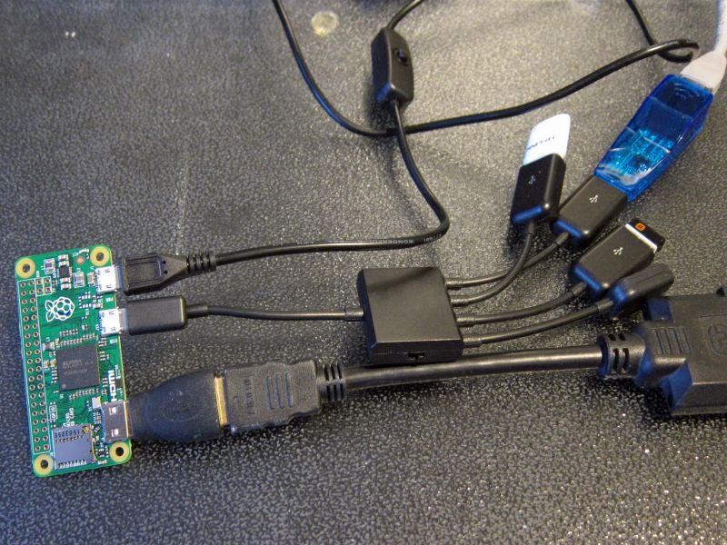

Photos: Hans Otten (left), J.A. Watson [via ZDNet] (right)
There are a few problems with this type of Raspberry Pi Zero configuration:
- We need an adapter for plugging in standard USB gamepads to the Pi Zero's USB OTG port.
- For multiple gamepads, we either need a USB hub or an adapter with a built-in hub.
- We need another adapter for plugging in a standard HDMI cable into the Pi Zero's mini-HDMI port
- Adapters are ugly!
- The USB port is on the same side of the device as the power and HDMI (ideally the USB ports are exposed on the front, with power and HDMI in back).
- Many of the generic Pi cases expose the GPIO pins (and other board features), which are necessary for some projects, but not this one.
Surely we could do better without spending a lot more time or money on this thing… right?
Planning
I started by putting together a list of sourcing and design considerations:
- I could add a Bluetooth module and avoid any exposed USB/gamepad ports, but wireless gamepads are more expensive, not to mention more of a hassle to keep charged; I'm sticking with USB for now.
- After researching and testing several gamepads on my own, the best value for the money seems to be the Buffalo Classic USB Gamepad. You may prefer something different or more expensive, but I haven't had any problem with these.
- No WiFi is necessary - the idea is to load some games onto an SD card, keep the SD card in the device, and avoid any more complexity.
- The SD card slot probably doesn't need to be accessible for everyday use.
- A power switch/button would be nice to avoid having to plug/unplug from the wall.
- The Pi Zero is really small - almost too small. Once cables are plugged into it, it seems more manageable and "friendly" in a slightly larger form-factor.
- The case should be easy to 3D print.
- Use a UL listed power supply (so we don't burn down the house).
- Keep it cheap.
- Keep it relatively simple to build.
These constraints helped narrow down the possible project components, and this is what I ended up with:
| Component | Price |
|---|---|
| Raspberry Pi Zero* | $5 |
| Stackable USB hub + 2.4A UL-listed Power Supply w/ Switch | $15 |
| 8 GB microSD Card | $7 |
| HDMI Cable | $2 |
| mini-HDMI to HDMI Adapter (or an adapter with the same dimensions to fit the enclosure below) | $3 |
| CPU Heatsink | $2 |
| Enclosure (generic ABS filament, 3D printed) | $2 |
| Cost without Gamepads | $36 |
| 2x USB Gamepads (~ $15/ea.) | $30 |
| Total Cost with Two Gamepads | $66 |
* If you don't live in the UK, you'll likely have to pay extra for shipping on the Raspberry Pi Zero. Most of the other components can be shipped for free, and if you purchase the Pi Zero in a kit (with some of the other required components), you may be able to offset the shipping price.
Enclosure Design
I went with a fairly minimal design for the case - a basic, no-frills rounded box. Here are some notable details that affected the design:
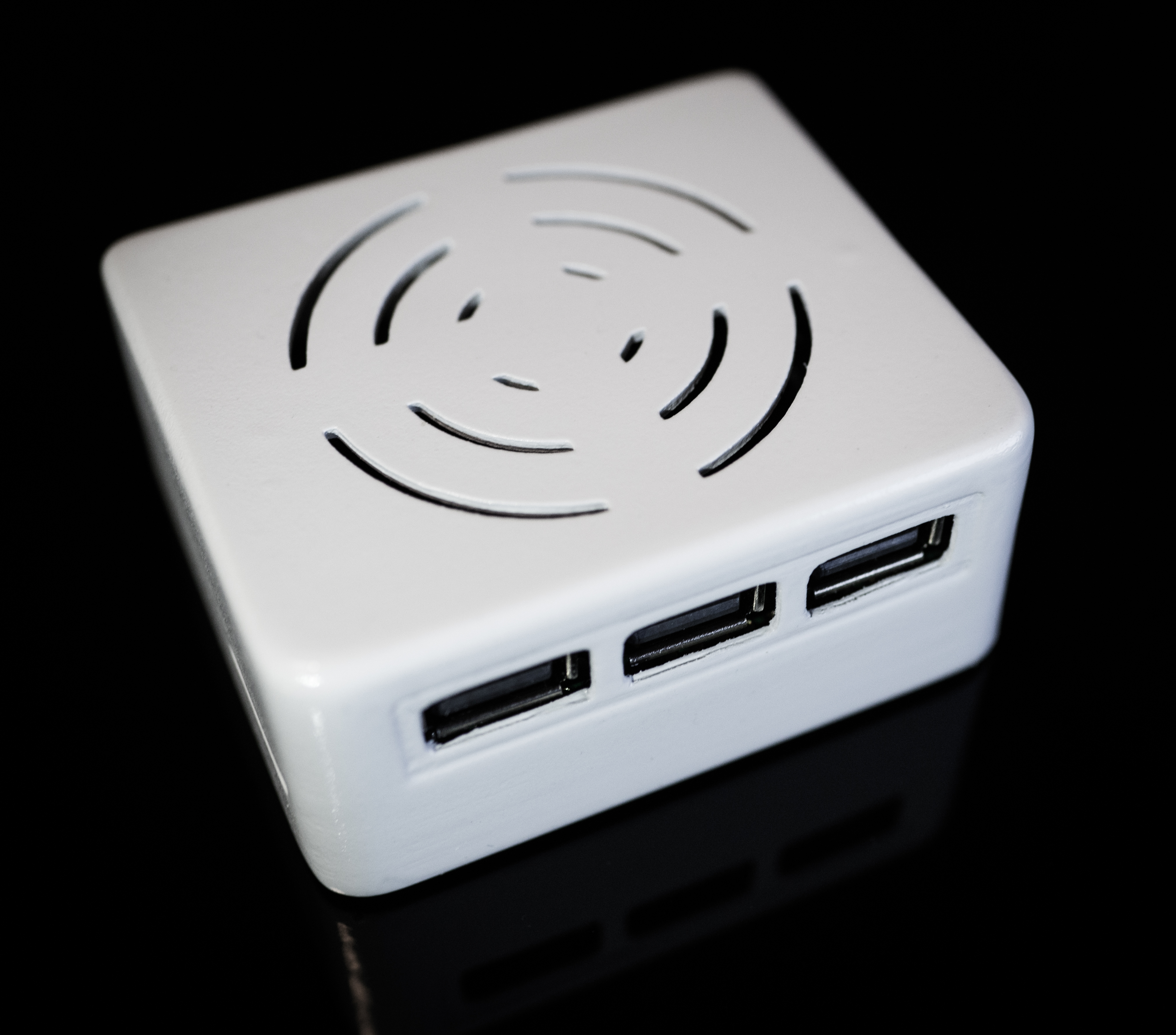
- The MakerSpot Stackable USB Hub gives us 3 USB ports on the side opposite the power and HDMI ports, so that made it a great choice for this project (we wanted the gamepad ports exposed on the front and everything else in back).
- With the added height of the USB Hub, the USB ports would either be exposed down close to the floor of the unit, or higher up. It looked better with the ports higher up.
- The cover for the case is located on the underside and recessed so as to be completely hidden when the device is sitting on a flat surface.
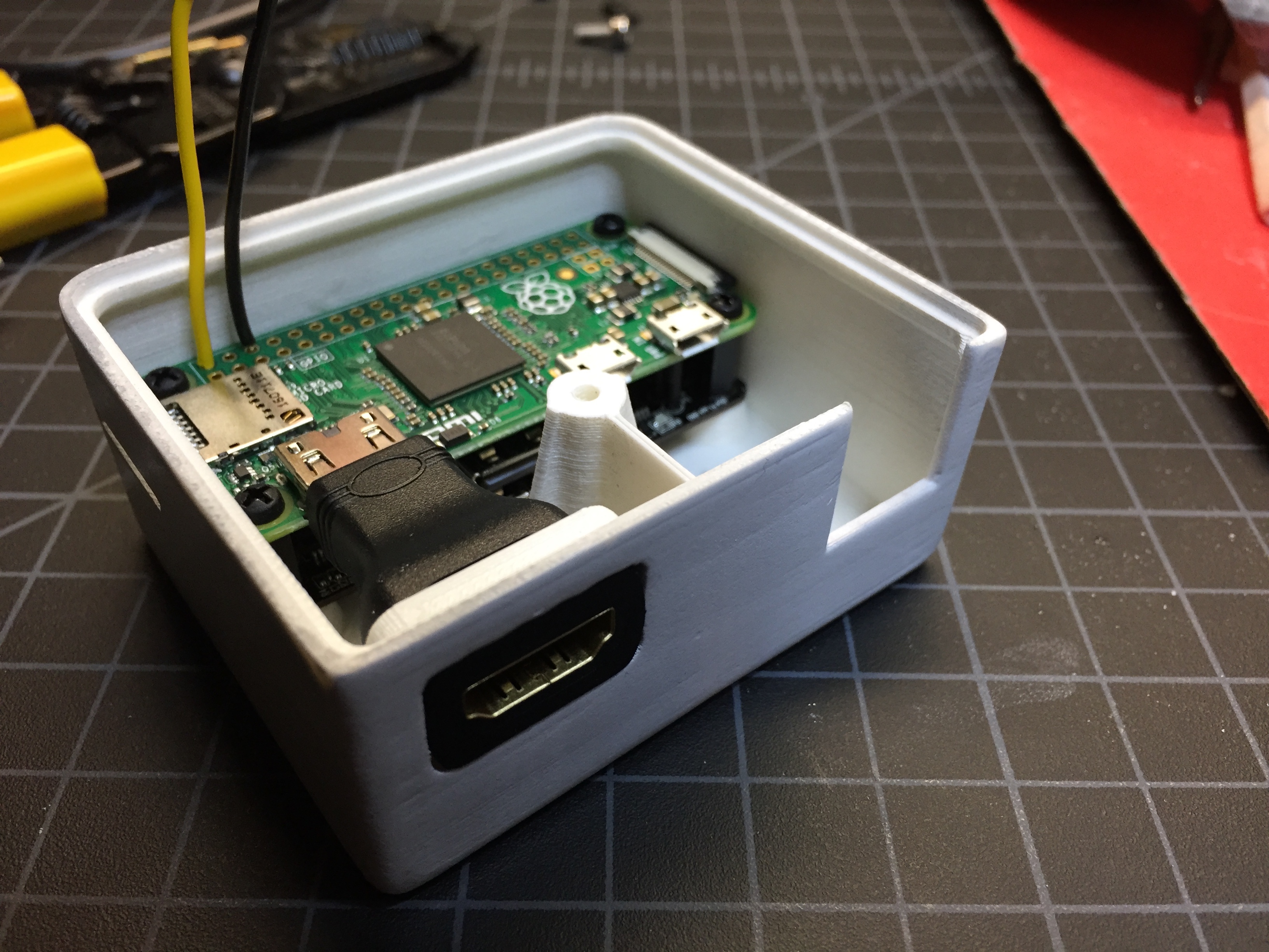
- The mini-HDMI to HDMI adapter is incorporated into the case itself to make things more tidy. It's not the most elegant solution ever, but it's easy, cheap, and makes for a friendlier experience for people who may have never dealt with mini-HDMI. This effectively gives the device dimensions that are closer to square (rather than the Pi Zero's oblong dimensions).
- While the Raspberry Pi Zero stays reasonably cool during normal operation (aided in part by the CPU heatsink), vents are added to the top of the enclosure to provide some airflow for better heat dissipation.
- The Micro-USB port for power will require less-frequent access than the other ports on the device. To avoid yet another adapter or extension within the enclosure, I opted to make that port accessible via a small recessed space on the back.
- By orienting the PCBs with the USB ports exposed near the top of the unit, the ports (not just USB, but also HDMI) are "upside-down" compared to what has become common orientation. As far as I understand, that's not strictly a standard, and most people won't notice the difference anyway.
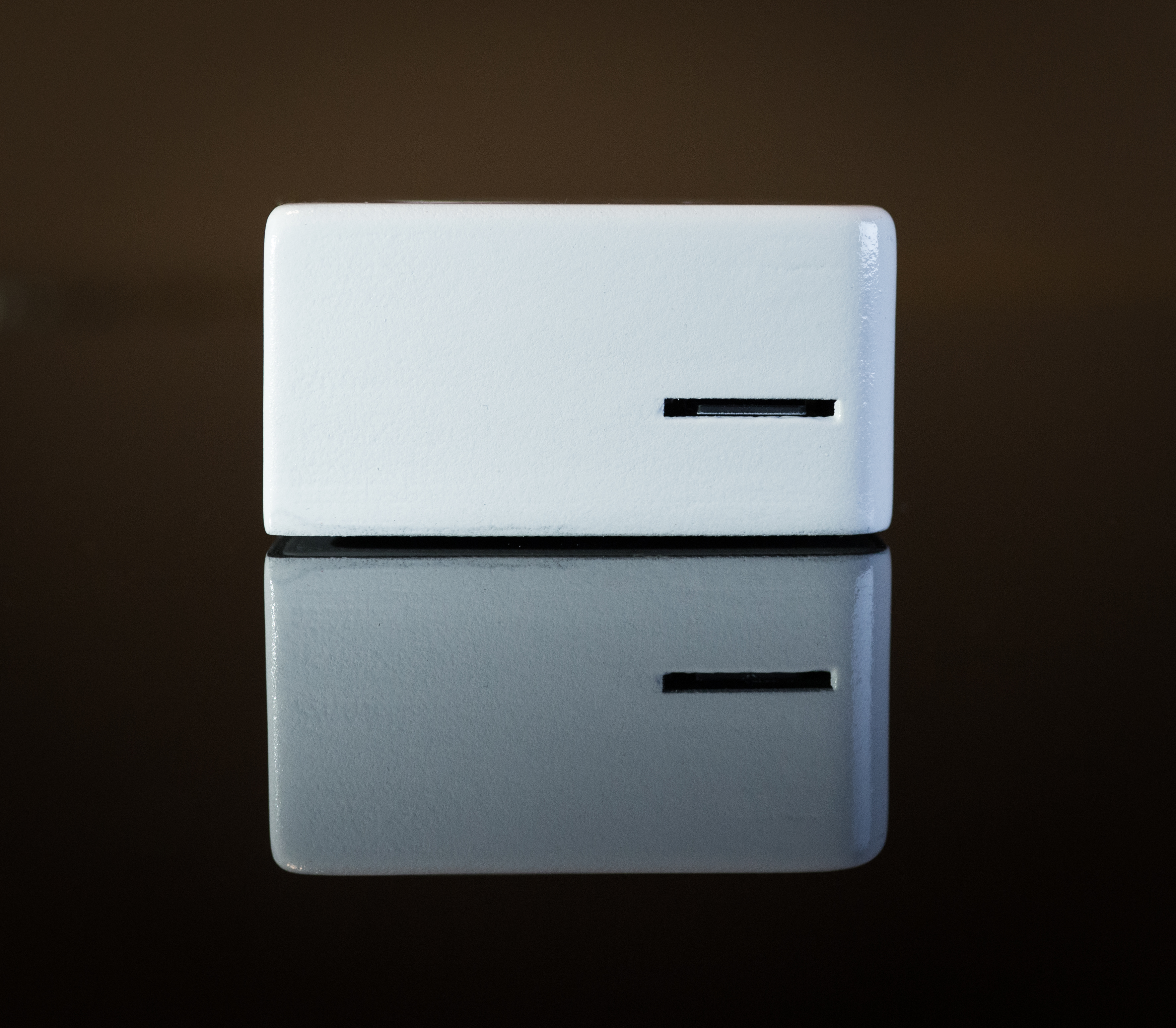
- The microSD card slot is accessible through a small slit in the side of the enclosure, but it's intended to be used only rarely (e.g., upgrading the system). A pair of fine-point tweezers is necessary for extraction of the card.
The case was designed in Fusion 360 with some parametric modeling. After 3 or 4 iterations (tweaking small things here and there), I came up with this:
Sketches and Renders
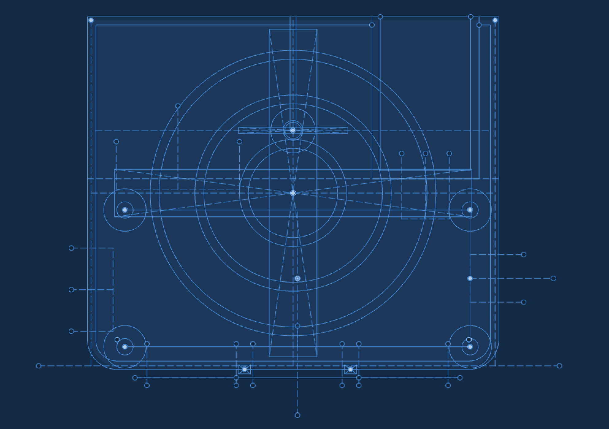
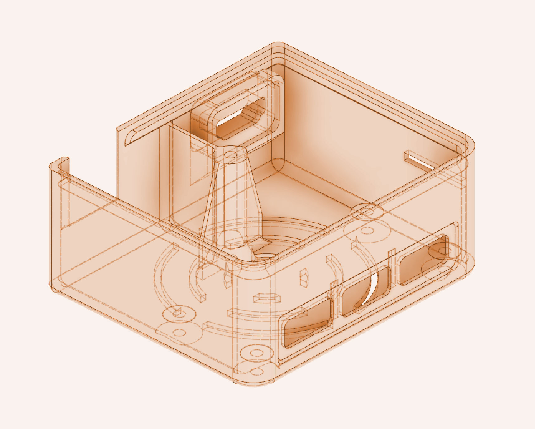
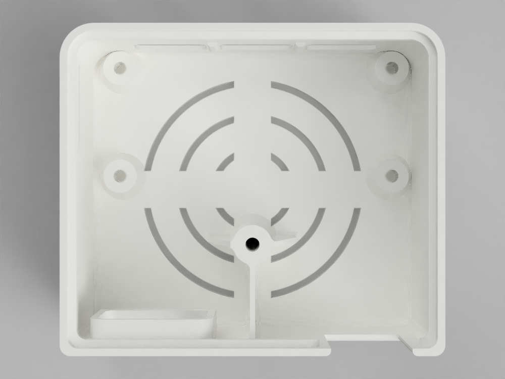
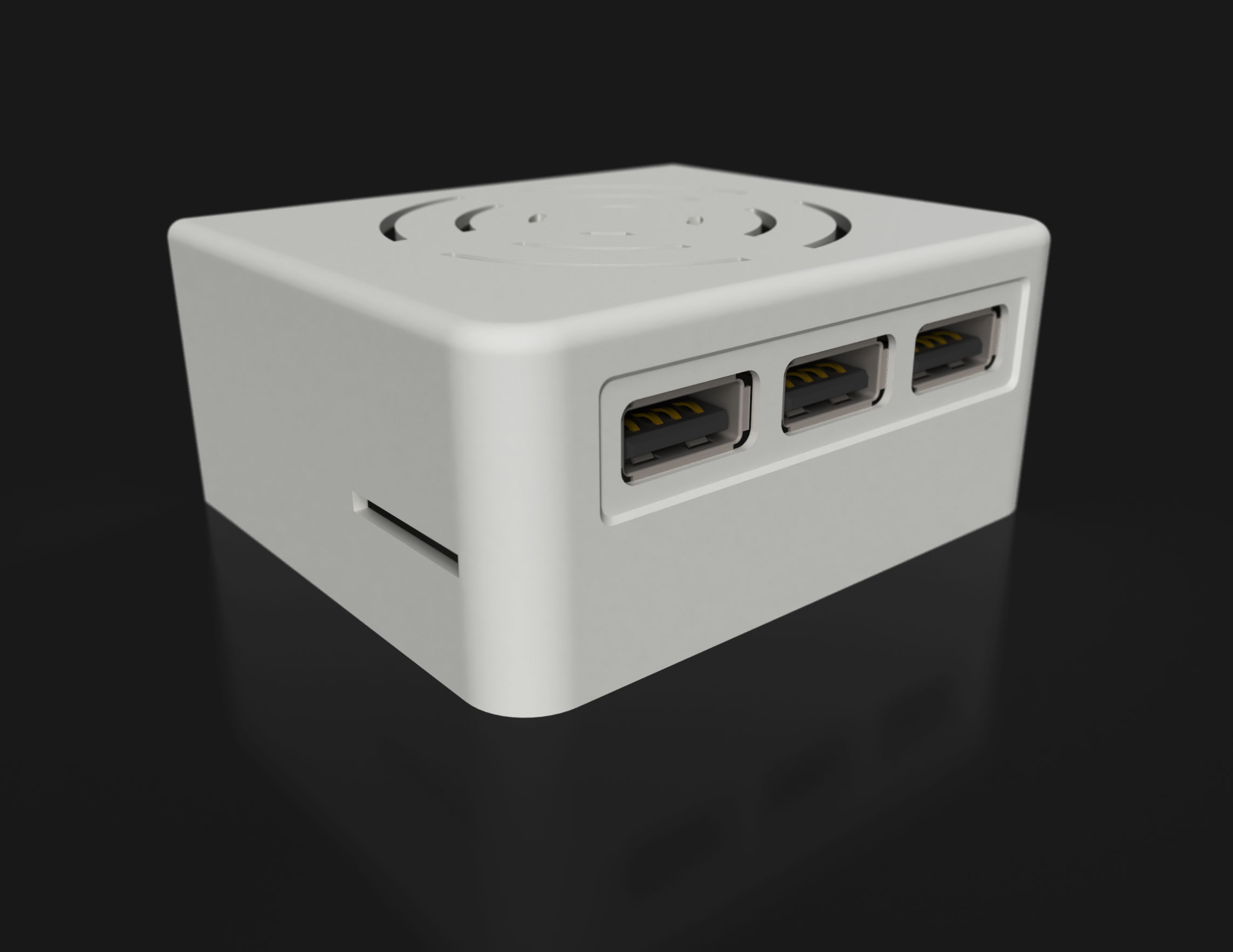
(links to the model files are at the bottom of this page)
3D Printing Process
A little over 3 hours on a modified Monoprice Maker Select v2
Assembly
- Using metal machine screws or a tap, create some threads in the mounting and bottom cover screw holes. The holes for mounting the PCB are M2.5, and the hole for the bottom cover is M3. I just use a metal screw of the appropriate size, drive it in (until it bottoms out for the PCB mounting holes, and just enough depth for your cover screw) and back it out. I use a nylon screw for the cover, but if you're going to use a metal screw for securing the cover, there's no need to create threads first. Just don't use nylon screws in holes that haven't been threaded with a metal screw/tap first or the plastic will destroy the screw threads. The stackable USB hub comes with its own set of nylon standoffs and screws, so we're going to use those later.
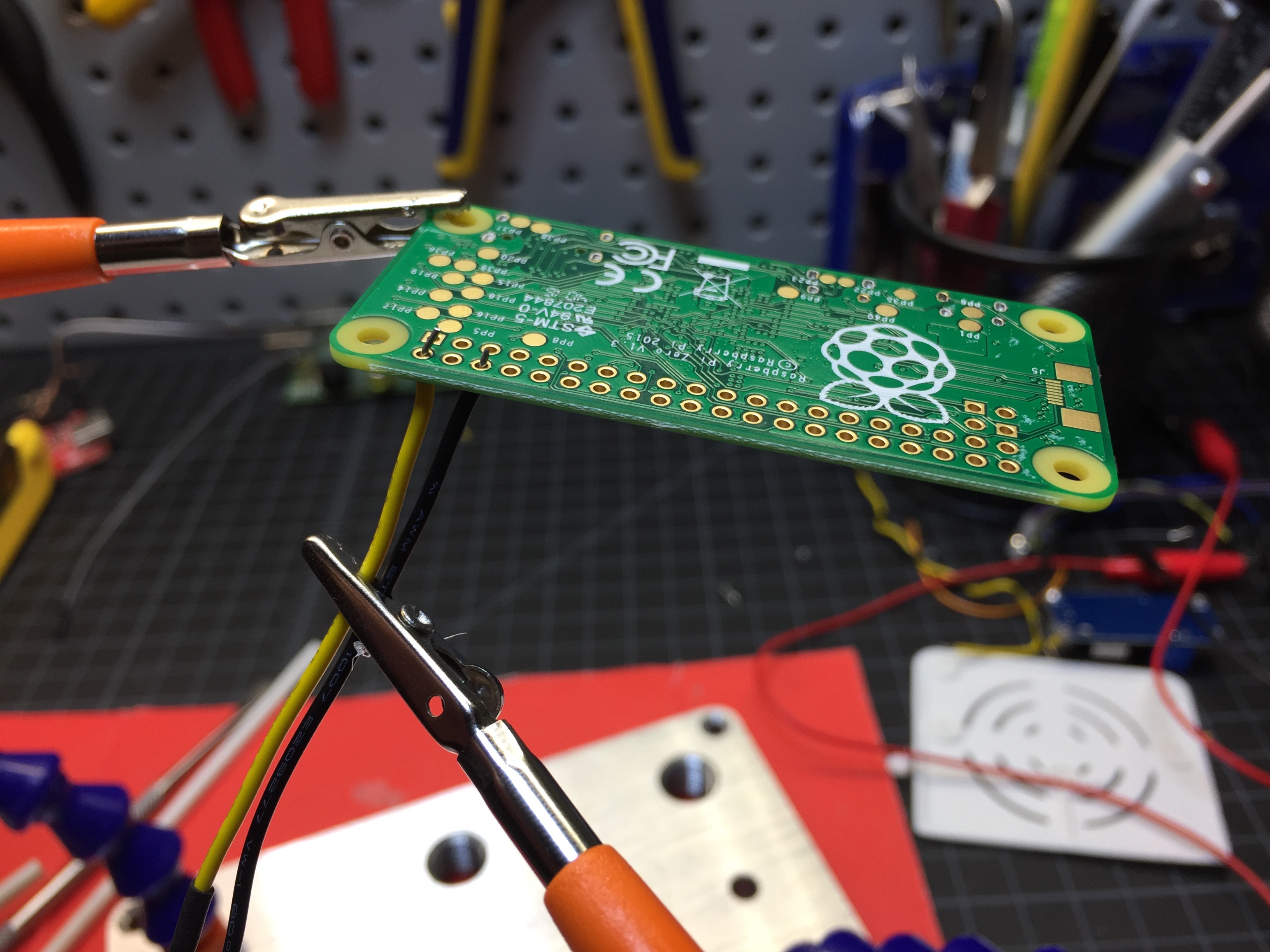
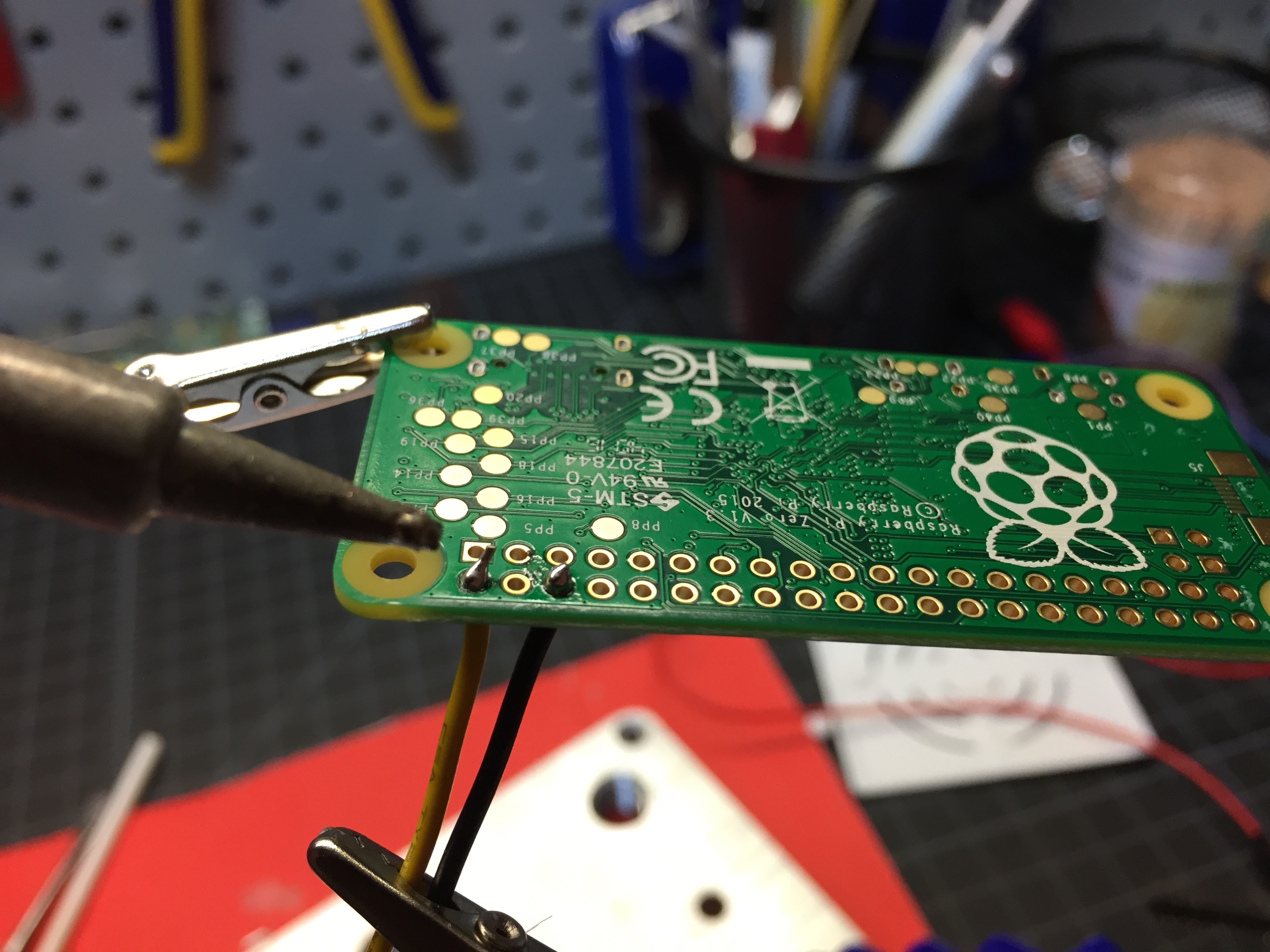
- (optional) If you want an extra LED status light for indicating when the device is on (the Pi Zero's built-in lights are not very bright through the enclosure), you can solder an LED to the Pi Zero board. In my case, I found a spare 5mm green LED, soldered a 100 ohm resistor to one of the leads (along with a short bit of solid core wire), applied some heat shrink tubing for insulation, and finally soldered the two wires to the +5v and ground pins of the Raspberry Pi Zero.
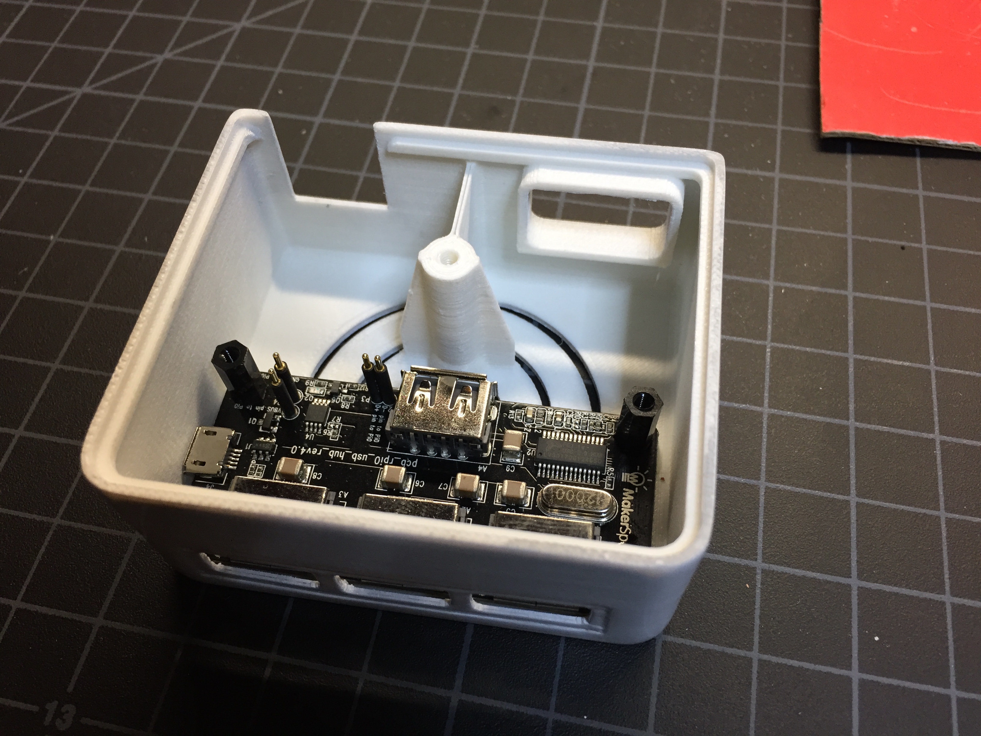
- Place the stackable USB hub (not attached to the Pi Zero yet!) into the enclosure ensuring that the three USB ports line up with the spaces in the enclosure. Screw the four M2.5 nylon standoffs (that come with the stackable USB hub) through the hub's mounting holes and into the holes of the enclosure. For added strength, add a drop or two of cyanoacrylate to the holes before tightening the standoffs. Don't over-tighten, but make sure the USB hub rests flush with the top of the holes of the enclosure.
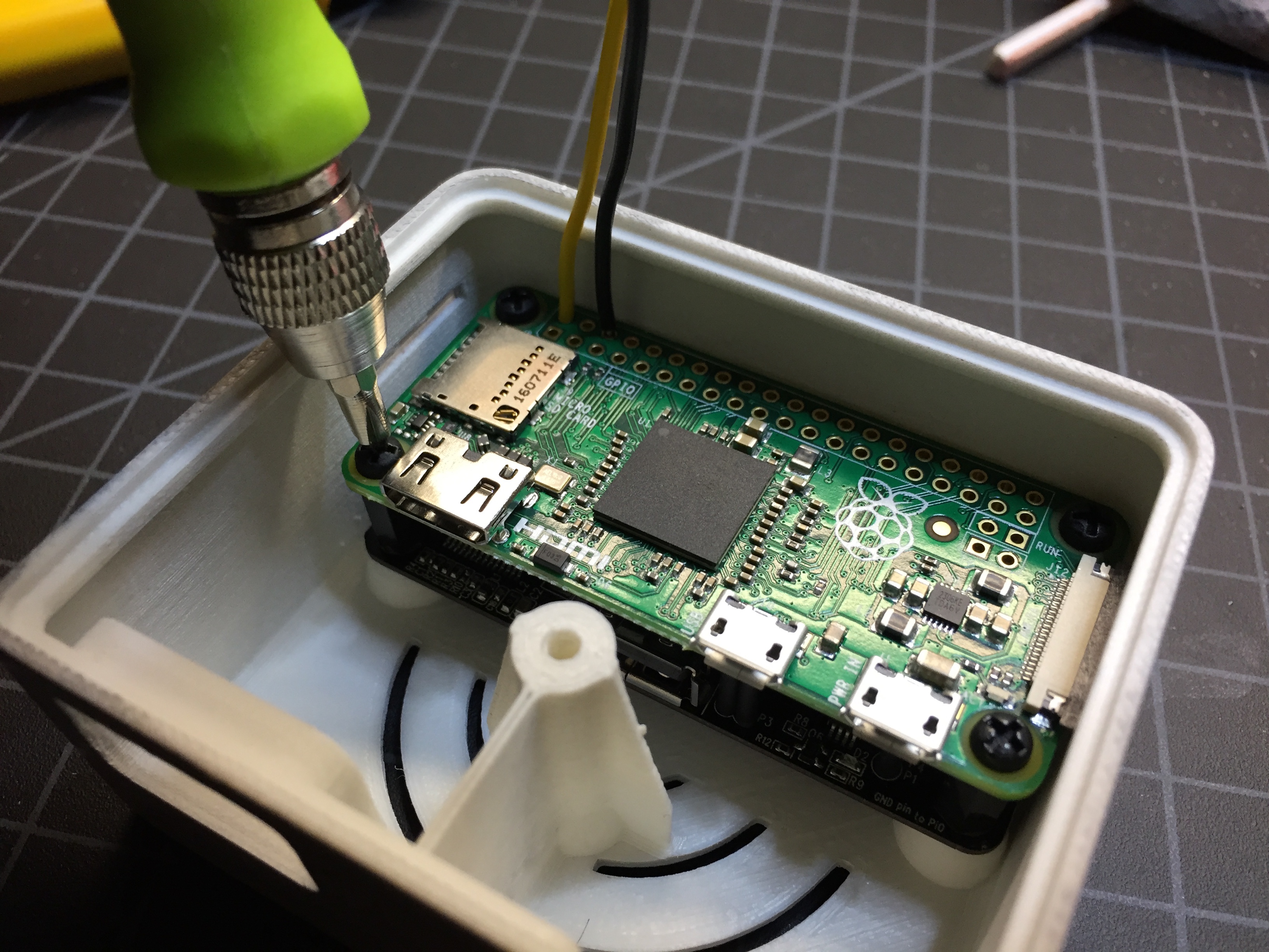
- Carefully place the Raspberry Pi Zero on top of the stackable USB hub, ensuring that the hub's pogo pins make contact with the correct pads on the Pi Zero. Use the 4 nylon screws (provided with the hub) to secure the Pi Zero to the USB hub standoffs.
- Insert the mini-HDMI to HDMI adapter through the hole in the back of the enclosure and into the mini-HDMI port on the Pi Zero.
- Using a hot glue gun, apply some hot glue around the area where the HDMI adapter meets the inside of the enclosure. This will prevent the adapter from being inadvertently pulled out of the case. It's also probably a good idea to add a few dabs of hot glue between the corners of the PCB(s) and the interior of the case. We're not using metal screws, so this will help keep the PCBs affixed to the case, especially when pressure is applied while attaching/removing controllers.
- Remove the adhesive backing from the heatsink and attach it to the Raspberry Pi Zero's CPU.
- (if wiring a power status LED) Route the LED and wiring to a location within the case to provide good visibility. For many plastics, the enclosure will be translucent enough (and the LED bright enough) to allow you to place it just about anywhere, as long as it's facing outward. I usually place the LED near the vent holes on the top of the enclosure so it can be seen even through opaque materials (by shining up through the vents). You could add a small bit of hot glue to keep the LED in place, or skip the glue if the wires are stiff enough to keep things from moving around. Just make sure the wires and LED don't get in the way of the bottom cover.
- Screw on the bottom cover with a short M3 screw.
- Use a computer to prepare the microSD card, loading the desired software, configuration, and games (info below).
- Insert the microSD card through the slot in the case, making sure it's oriented correctly for the Raspberry Pi Zero. You'll probably need a pair of tweezers or other sharp object to help push it fully into the Pi Zero microSD card slot (and for removal).
Assembly Photos


Finished Product
I painted the exterior of one of the enclosures (prior to assembly) to see how it would turn out. Here are some photos:


Software
There are several options for running emulation software on a Raspberry Pi. For tinkerers and tech-oriented people who want a lot of control and flexibility over the system, RetroPie is a great option.
For this build, however, I was interested in something that favors simplicity over customization. For that, I chose Recalbox. Even with Recalbox, there are quite a few configuration options that affect the appearance and behavior of the experience, so I took a bit of time to create a configuration that turns off some unnecessary features and keeps things straightforward and easy-to-use.
Specifically, the Raspberry Pi Zero has no built-in Ethernet or Wi-Fi (and we don't need networking), so we turn off Recalbox's HTTP manager, SSH, and REST API. And since we're using this exclusively for emulation, we disable Kodi. Finally, to keep things simple, we disable extra emulator menus and advanced settings that would normally be shown in the UI.
For games (commonly referred to as ROMs), unfortunately you're on your own. I don't endorse the downloading or use of ROMs for which you don't have a legal license. There are quite a few websites that offer free, fully-legal homebrew video game ROMs that you can download and play on this system. If you're looking for more mainstream classic titles, you may or may not have luck searching for them elsewhere. There's my Glomar response for the day.
(config files available for download below)
Final Thoughts
I'm fairly happy with the final result, and more importantly, my wife and kids (and some extended family) enjoy using the emulator device - and they don't need my help figuring out how to use it. It just works.
With that said, this is probably not the final iteration of the project. Here are at least a few things that could definitely be improved:
- Implement a switch- or button-activated power off function to cleanly shut down and power off the unit. This would help avoid the eventual possibility of corrupting data if the filesystem isn't in a consistent state when power is cut off. In practice, I think the risk of corruption is quite low, but it's still a concern.
- As mentioned, the ports should probably be flipped around the other way.
- Rather than relying on plastic screws and hot glue to keep the PCB attached to the case, use metal screws and nuts to keep things more securely in place. Alternatively, build the necessary standoffs and anchors into the enclosure itself for a press-fit hold on the PCB.
- Incorporate the power status light (and switch) into the case design.
- Expose 2 or 4 USB ports instead of 3. Not sure why exactly - 3 just seems a little… odd?
- Find a better way to expose the Micro-USB power port and HDMI port without resorting to the embedded adapter or recessed cavity in the design.
- Remove the microSD slot on the side, allowing for emergency access some other way.
… of course, if we're going to over-engineer this thing beyond a certain point, we might as well put together a custom board, create a plastic injection molded case, get the hardware certified, etc. and sell the thing. And of course, some people are doing just that.
But that would turn the project into a business enterprise, and it certainly wouldn't be as enjoyable as building it myself.
Downloads
Download 3D Files on Thingiverse
Download Recalbox Configuration Files (for Recalbox 4.0)
Note about Amazon.com: I originally linked to the corresponding products on Amazon.com above (using affiliate links to help offset the cost of keeping this website alive). The links were unobtrusive and obviously provided value to the visitors of this site wishing to build similar projects. Unfortunately, Amazon decided to decline my affiliate links/affiliation - of course, only after I had generated a few hundred dollars of sales for them (so they got the sales but didn't pay me anything for the referrals). They said I could reapply, so I did, generated more referral sales, and they again pulled my affiliate application, citing that my website lacks "original" or "beneficial" content. Whatever. I'd normally say "go ahead and buy this stuff from Amazon.com", but after the way they've treated me here, I have a hard time recommending them. Do us all a favor and buy this stuff somewhere else, not Amazon.com. :)